U N I T 6 RAY OPTICS
There are two ways of spreading light: to be the candle or the mirror that reflects it. — Edith Wharton
Learning Objectives
In this unit, the students are exposed to,
• The ray aspect of light.
• The phenomenon of reflection and refraction of light.
• The determination of speed of light.
• The concepts related to mirrors, lenses, prisms etc.
• The different phenomena like dispersion and scattering of light.
INTRODUCTION
Light is mystical. Yet, its behaviour is so fascinating. It is difficult to comprehend light as a single entity. The ray optics deals with light that is represented as a ray travelling in straight lines. Here, the geometrical constructs get the permanence to understand some of the characteristics of light and the phenomena associated with it. There are several other phenomena which can only be explained using wave optics, which we study in the next Unit. There is also a quantum aspect of light which we can study as quantum optics in graduate level courses.
Ray optics
Light travels in a straight line in a medium. Light may deviate in its path only when it encounters the boundary of another medium (or) an obstacle. A ray of light gives information only about the direction of light. It does not give information about the other characteristics like intensity and colour of light. However, a ray is a sensible representation of light in ray optics. The path of the light is called a ray of light and a bundle of such rays is called a beam of light. In this chapter, we can explain the phenomena of reflection, refraction, dispersion and scattering of light, using the ray depiction of light.
Reflection
The bouncing back of light into the same medium when it encounters a reflecting surface is called reflection of light. Any polished surface can reflect light. Mirrors which are silver coated at their back can reflect almost 90% of the light falling on them. The angle of incidence i and the angle of reflection r are measured with respect to the normal drawn to the surface at the point
of incidence of light. According to laws of reflection, (i) The incident ray, reflected ray and normal
to the reflecting surface are all coplanar (ie. lie in the same plane).
(ii) The angle of incidence i is equal to the angle of reflection r.
i = r (6.1)
The law of reflection is shown in Figure 6.1.
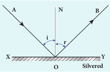
Figure 6.1 Reflection of light
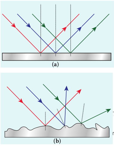
The laws of reflection are valid at each point for any reflecting surface whether the surface is flat (or) curved. If the reflecting surface is flat, then incident parallel rays after reflection come out as parallel rays as shown in Figure 6.2(a). If the reflecting surface is irregular, then the incident parallel rays after reflection come out as irregular rays (not parallel rays). Still the laws of reflection are valid at every point of incidence in irregular reflection as shown in Figure 6.2(b).
Angle of deviation due to reflection
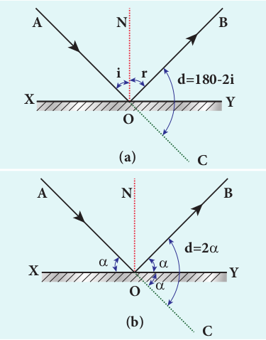
The angle between the direction of incident ray and the reflected ray is called angle of deviation due to reflection. It is calculated by a simple geometry as shown in Figure 6.3(a). The incident light is AO. The reflected light is OB. The un-deviated light is OC which is the continuation of the incident light. The angle between OB and OC is the angle of deviation d. From the geometry, it is written as, d = 180 – (i+r). As, i = r in reflection, we can write angle of deviation in reflection as,
d = 180 – 2i (6.2)
The angle of deviation can also be measured in terms of the glancing angle α which is measured between the incident ray AO and the reflecting plane surface XY as shown in Figure 6.3(b). By geometry, the angles ∠_AOX_ = α, ∠_BOY_ = α and ∠_YOC_ = α (all are same). The angle of deviation d is the angle ∠_BOC_. Therefore,
d = 2α (6.3)
EXAMPLE 6.1 Prove that for the same incident light when a reflecting surface is tilted by an angle θ, the reflected light will be tilted by an angle 2_θ_.
Solution AB is the reflecting surface as shown in the Figure. Both the incident ray IO and the reflected ray OR_1 subtend angle i with the normal N as the angle of incidence is equal to angle of reflection. When the surface AB is tilted to ¢ ¢_A B by an angle θ, the normal N is also is tilted to ′N by the same angle θ. Remember that the position of the incident ray IO remains unaltered. But the reflected ray now is OR_2. Now, in the tilted system, the angle of incidence, ∠_N’OI = i+θ and the angle of reflection, ∠_N’OR_2 = i+θ are the same. The angle between ON’ and _OR_1 is, ∠_N’OR_1 = i – θ. The angle tilted on the reflected light is the angle between _OR_1 and _OR_2 which is ∠_R_1_OR_2. From the geometry we can write,
∠_R_1_OR_2 = ∠_N’OR_2 – ∠_N’OR_1 = (i+θ) – (i–θ) ∠_R_1_OR_2 = 2_θ_.
Image formation in plane mirror
Let us consider a point object A placed in front of a plane mirror. The point of incidence is O on the mirror as shown in the Figure. 6.4(a).
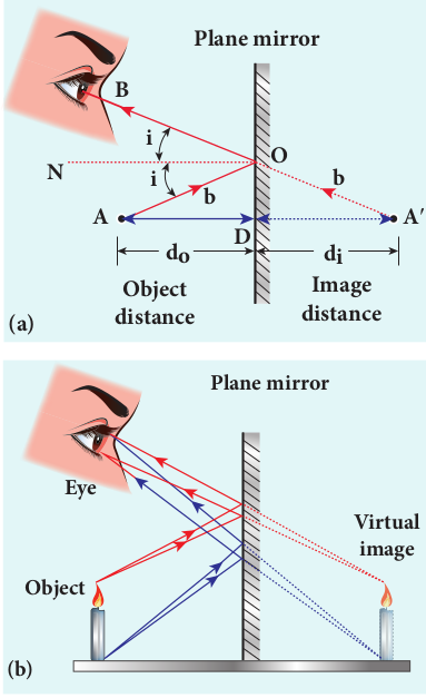
A light ray AO from the point object is incident on the mirror and it is reflected along OB. The normal is ON.
The angle of incidence ∠_AON_ = angle of reflection ∠_BON_
Another ray AD incident normally on the mirror at D is reflected back along DA. When BO and AD are extended backwards, they meet at a point A’. Thus, the rays appear to come from a point A’ which is behind the plane mirror. The object and its image are at equal perpendicular distances from the plane mirror which can be shown by the following explanation.
Angle ∠_AON_ = angle ∠_DAO_ [Since they are alternate angles]
Angle ∠_BON_ = angle ∠_O_ ¢_A D_ [Since they are corresponding angles]
Hence, it follows that angle, ∠_DAO_ = ∠_O_ ¢_A D_
The triangles ∆_ODA_ and ∆_OD_ ¢_A_ are congruent
∴ AD = ¢_A D_ This shows that the image distance di
inside the plane mirror is equal to the object distance do in front of the plane mirror.
The image formed by the plane mirror for extended object is shown in Figure 6.4(b).
Characteristics of the image formed by plane mirror
(i) The image formed by a plane mirror is virtual, erect and laterally inverted sidewise (left / right).
(ii) The size of the image is equal to the size of the object.
(iii) The image distance behind the mirror is equal to the object distance in front of the mirror.
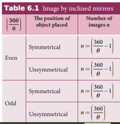
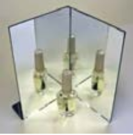
(iv) If an object is placed between two plane mirrors inclined at an angle θ, then the number of images n formed is given in Table 6.1 the images formed are shown in Figure 6.5.
Table 6.1 Image by inclined mirrors
EXAMPLE 6.2
What is the height of the mirror needed for a person to see his/her image fully on the mirror?
Solution Let us assume a person of height h is standing in front of a vertical plane mirror. The person could see his/her head when light from the head falls on the mirror and gets reflected to the eyes. Same way, light from the feet falls on the mirror and gets reflected to the eyes.
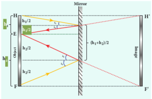
If the distance between his head H and eye E is h1 and distance between his feet F and eye E is h2. The person’s total height is, h. Here it is, h = h1 + h2
By the law of reflection, the angle of incidence and angle of reflection are the same for the two extreme reflections. The normals are now the bisectors of the angles between the incident and the reflected rays at the two points. By geometry, the height of the mirror needed is only half of the
height of the person. \(\frac{h_1+h_2}{2} = \frac{h}{2}\)
Does the height depend on the distance between the person and the mirror?