SPHERICAL MIRRORS
We shall now study about the reflections that take place in spherical surfaces.
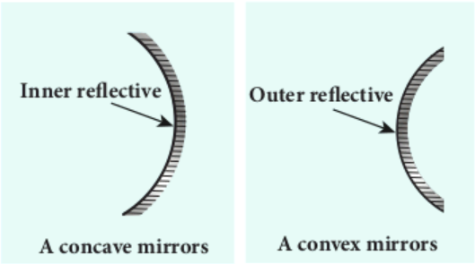
A spherical surface is a part cut from a hollow sphere. Spherical mirrors are generally constructed using glass. One surface of the glass is silvered. The reflection takes place at the other surface which is polished. If the polished surface of the mirror is convex it is called as convex mirror. These are shown in Figure 6.6.
We shall get familiarised with some of the terminologies pertaining to spherical mirrors.
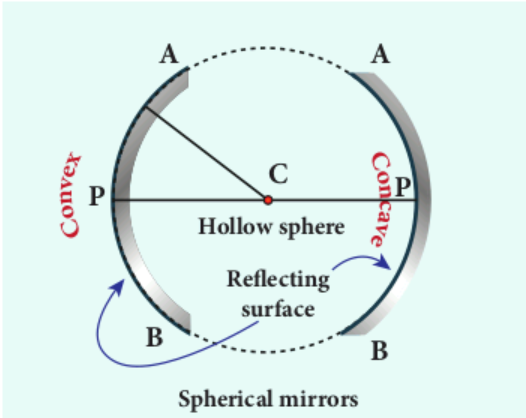
Centre of curvature: The centre of the sphere of which the mirror is a part is called the centre of curvature C of the mirror.
Radius of curvature: The radius of the sphere of which the spherical mirror is a part is called the radius of curvature R of the mirror.
Pole: The middle point on the spherical surface of the mirror (or) the geometrical centre of the mirror is called pole P of the mirror (or) optic centre.
Principal axis: The line joining the pole P and the centre of curvature C is called the principal axis of the mirror. The light ray travelling along the principal axis towards the mirror after reflection travels back along the same principal axis. It is also called optical axis
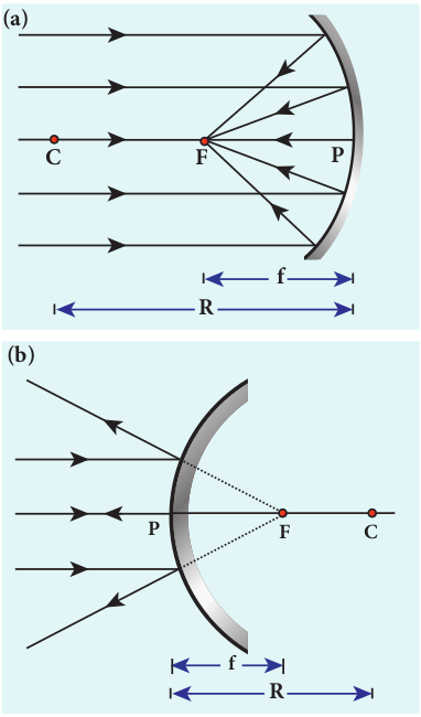
Focus (or) Focal point: Light rays travelling parallel and close to the principal axis when incident on a spherical mirror, converge at a point for concave mirror (or) appear to diverge from a point for convex mirror on the principal axis. This point is called the _focus (_or) focal point F of the mirror.
Focal length: The distance between the pole P and the focus F is called the focal length f of the mirror.
Focal plane: The plane through the focus and perpendicular to the principal axis is called the focal plane of the mirror.
All the above mentioned terms are shown in Figure 6.7 for both concave and convex mirrors.
Paraxial Rays and Marginal Rays
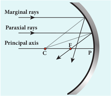
The paraxial rays are the rays which travel very close to the principal axis and make small angles with it. They fall on the mirror very close to the pole. On the other hand, the marginal rays are the rays which travel far away from the principal axis and make large angles with it. They fall on the mirror far away from the pole. These two rays behave differently (get focused at different points) as shown in Figure 6.8. In this chapter, we shall restrict our studies only to paraxial rays. As the angles made by the paraxial rays are very small, we can make good approximations.
Relation between f and R
Let C be the centre of curvature of the mirror. Consider a ray of light parallel to the principal axis is incident on the mirror at M. It passes through the principal focus F after reflection. The geometry related to this is shown in Figure 6.9(a). The line CM is the normal to the mirror at M. Let i be the angle of incidence and the same will be the angle of reflection.
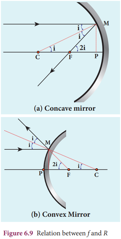
If MP is the perpendicular from M to the principal axis, then
The angles ∠ MCP = i and ∠ MFP = 2_i_ From right angle triangles ∆ MCP and
∆ MFP, we can write,
\(\tan i=\frac{P M}{P C} \text { and } \tan 2 i=\frac{P M}{P F}\)As the angles are small, \(\tan i \approx i\) and \(\tan 2 i \approx 2 i\) ,
\(i=\frac{P M}{P C} \text { and } 2 i=\frac{P M}{P F}\)Simplifying further,
\(2 \frac{P M}{P C}=\frac{P M}{P F} ; 2 P F=P C\)\(P F\) is focal length \(f\) and \(P C\) is the radius of curvature \(R\) .
\(2 f=R \quad \text { (or) } \quad \mathrm{f}=\frac{R}{2}\)Equation (6.4) is the relation between $f$ and $R$. The construction is shown for convex mirror in figure 6.9(b)
Image formation in spherical mirrors
The image formed by spherical mirror can be found by ray construction called image tracing. To locate an image point, a minimum of two rays must meet at that point. We can use at least any two of the following four rays as shown in Figure 6.10.
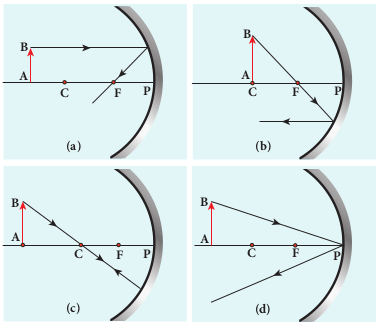
(i) A ray parallel to the principal axis after reflection will pass (or appear to pass) through the principal focus. (Figure 6.10(a))
(ii) A ray passing (or appear passing) through the principal focus, after reflection will travel parallel to the principal axis. (Figure 6.10(b))
(iii) A ray passing through the centre of curvature retraces its path after reflection as it is a normal incidence. (Figure 6.10(c))
(iv) A ray falling on the pole will get reflected as per law of reflection keeping principal axis as the normal. (Figure 6.10(d))
Cartesian sign convention
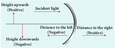
While tracing the image, we would normally come across the object distance u, the image distance v, the object height h, the image height ′h , the focal length f and the radius of curvature R. A system of signs for these quantities must be followed so that the relations connecting them are consistent in all types of physical situations. We shall follow the Cartesian sign convention which is now widely used. It is given below and also shown in Figure 6.11.
(i) The Incident light is taken as if it is travelling from left to right (i.e. object on the left of mirror).
(ii) All the distances are measured from the pole of the mirror (pole is taken as origin).
(iii) The distances measured to the right of pole along the principal axis are taken as positive.
(iv) The distances measured to the left of pole along the principal axis are taken as negative.
(v) Heights measured upwards perpendicular to the principal axis are taken as positive.
(vi) Heights measured downwards perpendicular to the principal axis, are taken as negative.
Mirror equation
The mirror equation establishes a relation among object distance u, image distance v and focal length f for a spherical mirror.
An object AB is considered on the principal axis of a concave mirror beyond the centre of curvature C. The image formation is shown in the Figure 6.12. Let us consider three paraxial rays from point B on the object. The first paraxial ray BD travells parallel to the principal axis. It is incident on the concave mirror at D, close to the pole P. It is reflected back through the focus F. The second paraxial ray BP is incident at the pole P. It is reflected along _PB_´. The third paraxial ray BC passing through centre of curvature C, falls normally on the mirror at E. It is reflected back along the same path. The three reflected rays intersect at the point ′ ′A B . A perpendicular drawn as ′ ′A B to the principal axis gives the real, inverted image.
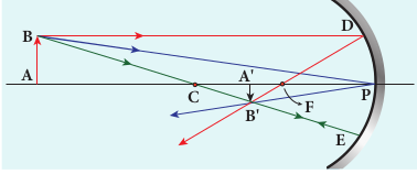
As per law of reflection, the angle of incidence \(\angle B P A\) is equal to the angle of reflection \(\angle B^{\prime} P A^{\prime}\) .
The triangles \(\triangle B P A\) and \(\triangle B^{\prime} P A^{\prime}\) are similar. Thus, from the rule of similar triangles,
\(\frac{A^{\prime} B^{\prime}}{A B}=\frac{P A^{\prime}}{P A}\)The other set of similar triangles are, \(\triangle D P F\) and \(\triangle B^{\prime} A^{\prime} F\) . ( P D is almost a straight vertical line) \(\frac{A^{\prime} B^{\prime}}{P D}=\frac{A^{\prime} F}{P F}\)
As, PD=AB the above equation becomes,
\(\frac{A^{\prime} B^{\prime}}{A B}=\frac{A^{\prime} F}{P F}\)From equations (6.5) and (6.6) we can write,
\(\frac{P A^{\prime}}{P A}=\frac{A^{\prime} F}{P F}\)As, \(A^{\prime} F=P A^{\prime}-P F\) , the above equation becomes,
\(\frac{P A^{\prime}}{P A}=\frac{P A^{\prime}-P F}{P F}\)We can apply the sign conventions for the various distances in the above equation.
P A=-u,
\(P A^{\prime}=-v, \quad P F=-f\)All the three distances are negative as per sign convention, because they are measured to the left of the pole. Now, the equation (6.7) becomes,
\(\frac{-v}{-u}=\frac{-v-(-f)}{-f}\)On further simplification, \(\frac{v}{u}=\frac{v-f}{f} ; \quad \frac{v}{u}=\frac{v}{f}-1\)
Dividing both sides with \(\mathrm{v}\) ,
\(\frac{1}{u}=\frac{1}{f}-\frac{1}{v}\)After rearranging,
\(\frac{1}{v}+\frac{1}{u}=\frac{1}{f}\)The equation (6.8) is called mirror equation. Although this equation is derived for a special situation shown in Figure (6.12), it is also valid for all other situations with any spherical mirror. This is because proper sign convention is followed for u, v and f in equation (6.7).
Lateral magnification in spherical mirrors
The lateral (or) transverse magnification m is defined as the ratio of the height of the image to the height of the object.The height of the object and image are measured perpendicular to the principal axis.
magnification \((m)=\frac{\text { height of theimage }\left(h^{\prime}\right)}{\text { height of the object }(h)}\)
\(m=\frac{h^{\prime}}{h}\)Applying proper sign conventions for equation (6.5),
\(\frac{A^{\prime} B^{\prime}}{A B}=\frac{P A^{\prime}}{P A}\) \(A^{\prime} B^{\prime}=-h^{\prime}, \mathrm{AB}=\mathrm{h}, P A^{\prime}=-v, P A=-u\) \(\frac{-h^{\prime}}{h}=\frac{-v}{-u}\)On simplifying we get,
\(m=\frac{h^{\prime}}{h}=-\frac{v}{u}\)Using mirror equation, we can further write the magnification as,
\(m=\frac{h^{\prime}}{h}=\frac{f-v}{f}=\frac{f}{f-u}\)The students are advised to refresh themselves with the image tracing
EXAMPLE 6.3
An object is placed at a distance of 20.0 cm from a concave mirror of focal length 15.0 cm.
(a) What distance from the mirror a screen should be placed to get a sharp image? (b) What is the nature of the image?
Solution Given, \( f=-15 \mathrm{~cm}, u=-20 \mathrm{~cm} \)
(a) Mirror equation, \(\frac{1}{v}+\frac{1}{u}=\frac{1}{f}\)
Rewriting to find \(\mathrm{v}, \quad \frac{1}{v}=\frac{1}{f}-\frac{1}{u}\)
Substituting for \(\mathrm{f}\) and \(\mathrm{u}, \frac{1}{v}=\frac{1}{-15}-\frac{1}{-20}\)
\(\frac{1}{v}=\frac{(-20)-(-15)}{300}=\frac{-5}{300}=\frac{-1}{60}\) \(v=-60.0 \mathrm{~cm}\)The screen is to be placed at distance 60.0
\(\mathrm{cm}\) to the left of the concave mirror.
(b) Magnification, \(m=\frac{h^{\prime}}{h}=-\frac{v}{u}\)
\(m=\frac{h^{\prime}}{h}=-\frac{(-60)}{(-20)}=-3\)As the sign of magnification is negative, the image is inverted.
As the magnitude of magnification is 3 , the image is enlarged three times.
As the image is formed to the left of the concave mirror, the image is real.
EXAMPLE 6.4
A thin rod of length f /3 is placed along the optical axis of a concave mirror of focal length f such that one end of image which is real and elongated just touches the respective end of the rod. Calculate the longitudinal magnification.
Solution
\( \begin{aligned} & \text { longitudinal } \\ & \text { magnification }\end{aligned}\left(m_{l}\right)=\frac{\text { length of image }\left(l^{\prime}\right)}{\text { length of object }(l)}\) Given: length of object, \(l=\frac{f}{3}\)
For the given condition, the image formation is shown in the figure.
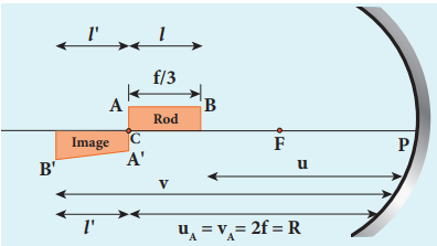
Let, \(l^{\prime}\) be the length of the image, then
\(m_{l}=\frac{l^{\prime}}{l}=\frac{l^{\prime}}{f / 3}\) (or) \(l^{\prime}=\frac{m_{l} f}{3}\)
Image of one end coincides with the respective end of object. Thus, the coinciding end must be at centre of curvature.
\(u_{B}=u_{A}-\frac{f}{3}=2 f-\frac{f}{3}=\frac{5 f}{3}\) \(v_{B}=u_{B}+l+l\) \(v_{B}=\frac{5 f}{3}+\frac{f}{3}+\frac{m_{l} f}{3}=\frac{f\left(6+m_{l}\right)}{3}\)Mirror equation, \(\frac{1}{v}+\frac{1}{u}=\frac{1}{f}\)
\(\frac{1}{-\left(\frac{f\left(6+m_{l}\right)}{3}\right)}+\frac{1}{-\left(\frac{5 f}{3}\right)}=\frac{1}{-f}\)After simplifying,
\(\frac{3}{f\left(6+m_{l}\right)}+\frac{3}{5 f}=\frac{1}{f} ; \frac{3}{\left(6+m_{l}\right)}=\frac{2}{5}\) \(6+m_{l}=\frac{15}{2} ; m_{l}=\frac{15}{2}-6\) \(m_{l}=\frac{3}{2}=1.5\)