INTERFERENCE
The phenomenon of superposition of two light waves which produces increase in intensity at some points and decrease in intensity at some other points is called interference of light.
Superposition of waves refers to addition of waves. The concept of superposition of mechanical waves is studied in (XI Physics 11.7). When two waves simultaneously pass through a particle in a medium, the resultant displacement of that particle is the vector addition of the displacements due to the individual waves. The resultant displacement will be maximum or minimum depending upon the phase difference between the two superimposing waves. These concepts hold good for light as well.
Let us consider two light waves from the two sources S1 and S2 meeting at a point P as shown in Figure 7.6.

The wave from S1 at an instant t at P is, \[ y_1 = a_1 \sin(\omega t) \] (7.6)
\[ y_2 = a_2 \sin(\omega t + \phi) \] (7.7)
The two waves have different amplitudes a1 and a2, same angular frequency ω, and a phase difference of ϕ between them. The resultant displacement will be given by,
$$ y=y_1+y_2 = a_1 \sin(\omega t) + a_2 \sin(\omega t + \phi) $$
The simplification of the above equation by using trigonometric identities as done in (XI Physics 11.7) gives,
$$ y = A \sin(\omega t + \theta) $$ where, $$A = \sqrt{a_{1}^2 + a_{2}^2 + 2a_{1}a_{2}\cos\phi} \quad \text{(7.10)}$$ $$\theta = \tan^{-1}\left(\frac{a_{2}\sin\phi}{a_{1} + a_{2}\cos\phi}\right) \quad \text{(7.11)}$$ The resultant amplitude is maximuim $$A_{\text{max}} = \sqrt{(a_{1} + a_{2})^2} \quad \text{when } \phi = 0, \pm 2\pi, \pm 4\pi, \ldots \quad \text {(7.12)}$$ The resultant amplitude is minimuim, $$A_{\text{min}} = \sqrt{(a_{1} - a_{2})^2} \quad \text{when } \phi = \pm\pi, \pm 3\pi, \pm 5\pi, \ldots \quad \text{(7.13)}$$ The intensity of light is proportional to square of amplitude, $$ I \propto A^2$$ Now, squaring equation (7.10) on both sides, $$I = I_{1} + I_{2} + 2\sqrt{I_{1} \cdot I_{2}} \cdot \cos \phi \quad \text{(7.15)}$$
In equation (7.15) if the phase difference, ϕ = 0, ±2π, ±4π. . . , it corresponds to the condition for maximum intensity of light called constructive interference.
The resultant maximum intensity is, $$I_{\text{max}} \propto (a_{1} + a_{2})^2 \quad $$ $$ I_{\text{max}} = I_{1} + I_{2} + 2\sqrt{I_{1}I_{2}}$$ (7.16) In equation (7.15) if the phase difference, ϕ = ±π, ±3π, ±5π. . . , it corresponds to the condition for minimum intensity of light called destructive interference.
The resultant minimum intensity is, $$ I_{\text{min}} \propto (a_{1} - a_{2})^2 \quad $$ $$\quad I_{\text{min}} = I_{1} + I_{2} - 2\sqrt{I_{1} \cdot I_{2}} \quad \text{(7.17)}$$ As a special case, if a1 = a2 = a, then equation (7.10). becomes, $$ {A} = \sqrt{2a^2 + 2a^2 \cos \phi} = \sqrt{2a^2(1 + \cos \phi)} = \sqrt{2a^2 \cos^2\left(\frac{\phi}{2}\right)} $$ $$A = 2a \cos\left(\frac{\phi}{2}\right) \quad \text{(7.18)} $$ $$I \propto 4a^2 \cos^2\left(\frac{\phi}{2}\right) \quad\text{[} I_{0} \propto A^2 \text{]} \text{(7.19)}$$
$$I = 4I_{0} \cos^2\left(\frac{\phi}{2}\right) \quad \text{[} I_{0} \propto a^2 \text{]} \quad \text{(7.20)}$$ $$ I_{\text{max}} = 4I_{0} \quad \text{when } \phi = 0, \pm 2\pi, \pm 4\pi, \ldots \quad \text{(7.21)}$$ $$ I_{\text{min}} = 0 \quad \text{when } \phi = \pm\pi, \pm 3\pi, \pm 5\pi, \ldots \quad \text{(7.22)}$$ We conclude that the phase difference ϕ, between the two waves decides the intensity of light at that point where the two waves meet.
EXAMPLE 7.2
Two light sources with amplitudes 5 units and 3 units respectively interfere with each other. Calculate the ratio of maximum and minimum intensities.
Solution
Amplitudes, a1 = 5, a2 = 3
Resultant amplitude, $$ A = \sqrt{a_1^2 + a_2^2 + 2a_1a_2\cos \phi}$$
Resultant amplitude is maximum when,
$$ \phi = 0, \quad \cos 0 = 1,A_{\text{max}} = \sqrt{a_1^2 + a_2^2 + 2a_1a_2} $$ $$ A_{\text{max}} = \sqrt{(a_1 + a_2)^2} = \sqrt{(5 + 3)^2} = \sqrt{8^2}=8units$$ Resultant amplitude is minimum when, $$ \phi = \pi, \quad \cos \pi = -1,A_{\text{min}} = \sqrt{a_1^2 + a_2^2 - 2a_1a_2} $$
$$ A_{\text{min}} = \sqrt{(a_1 - a_2)^2} = \sqrt{(5 - 3)^2} = \sqrt{2^2}=2units$$
$$ I \propto A^2 $$ $$ \frac{I_{\text{max}}}{I_{\text{min}}} = \left(\frac{A_{\text{max}}}{A_{\text{min}}}\right)^2 $$ Substituting, $$ \frac{I_{\text{max}}}{I_{\text{min}}} = \left(\frac{8}{2}\right)^2 = \frac{64}{4} = 16 (or)$$ $$ {I_{\text{max}}}:{I_{\text{min}}} = 16:1 $$ EXAMPLE 7.3 Two light sources of equal amplitudes interfere with each other. Calculate the ratio of maximum and minimum intensities. Solution Let the amplitude be a. The intensity is, $$I \propto 4a^{2}\cos^{2}\left(\frac{\phi}{2}\right) \quad $$ or$$ \quad I = 4I_{0}\cos^{2}\left(\frac{\phi}{2}\right) $$ Resultant intensity is maximum when, $$ \phi = 0, \cos 0 = 1, I_{\text{max}} \propto 4a^{2}$$ Resultant amplitude is minimum when, $$\phi = \pi, \cos\left(\frac{\pi}{2}\right) = 0, I_{\text{min}} = 0$$
$$I_{\text{max}}\ratio{I_{\text{min}}} = {4a^{2}}\ratio{0}$$
Phase difference and path difference
Phase is the angular position of vibration when a wave is progresses, there is a relation between the phase of the vibration and the path travelled by the wave. We can express the phase in terms of path and vice versa. In the path of the wave, one wavelength λ corresponds to a phase of 2π as shown in Figure 7.7. A path difference δ corresponds to a phase difference ϕ as given by the equation,

δ = nλ where, n = 0, 1, 2, 3 . . . (7.24)
For destructive interference, the phase difference should be, ϕ = π, 3π, 5π . . . Hence, the path difference must be, d l l =
In general, the half integral multiples of λ.
Formulas EXAMPLE 7.5
The wavelength of a light is 450 nm. How much phase it will differ for a path of 3 mm?
Solution
Wavelength, $$ \lambda = 450 nm = 450 \times 10^{-9} m $$
Path difference, $$\delta = 3 mm = 3 \times 10^{-3} m $$
Relation between phase difference and path difference, Substituting,
$$\phi = \frac{2\pi}{\lambda} \times \delta $$
Substituting the given values:
$$ \phi = \frac{2\pi}{450 \times 10^{-9}} \times 3 \times 10^{-3} = \frac{\pi}{75} \times 10^{6} $$
Therefore,
$$ \phi = \frac{\pi}{75} \times 10^{6} , \text{rad} = 4.19 \times 10^{4} , \text{rad} $$
Coherent sources
Two light sources are said to be coherent if they produce waves which have same phase or constant phase difference, same frequency or wavelength (monochromatic), same waveform and preferably same amplitude. Coherence is a property of waves that enables to obtain stationary interference patterns. Two independent monochromatic sources can never be coherent, because they may emit waves of same frequency and same amplitude, but not with same phase. This is because, atoms while emitting light, produce change in phase due to thermal vibrations. Hence, these sources are said to be incoherent sources.
To obtain coherent light waves, we have the following three techniques.
(i) Wavefront division
(ii) Intensity (or) Amplitude division
(iii) Source and Images.
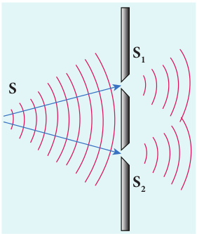
(i) Wavefront division: This is the most commonly used method for producing coherent sources. We know a point source produces spherical wavefronts. All the points on the wavefront are at the same phase. If two points are chosen on the wavefront by using a double slit, the two points will act as coherent sources as shown in Figure 7.8.
(ii) Intensity (or) Amplitude division: If we allow light to pass through a partially silvered mirror (beam splitter), both reflection and refraction take place simultaneously. As the two light beams are obtained from the same light source, the two divided light beams will be coherent beams. They will be either in-phase or at constant phase difference as shown in Figure 7.9. Instruments like Michelson’s interferometer, Fabray-Perrot etalon work on this principle.

(iii) Source and Images: In this method a source and its images will act as a set of coherent sources, because the source and its image will have waves in-phase (or) constant phase difference as shown in Figure 7.10. The Instrument, Fresnel’s biprism uses two virtual images of the source as two coherent sources and the instrument, Lloyd’s mirror uses a source and its one virtual image as two coherent sources.

Double slit as coherent sources
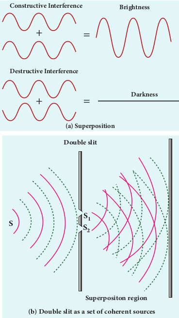
Double slit uses the principle of wavefront division. Two slits S1 and S2 illuminated by a single monochromatic source S act as two coherent sources. The waves from them travel in the same medium and superpose. The constructive and destructive interference formed by them are shown in Figure 7.11(a). The crests of the waves are shown by thick continuous lines and troughs are shown by broken lines in Figure 7.11(b).
At points where the crest of one wave meets the crest of the other wave (or) the trough of one wave meets the trough of the other wave, the waves are in-phase. Hence, the displacement is maximum and these points appear bright as a result of this constructive interference.
At points where the crest of one wave meets the trough of the other wave and vice-versa, the waves are out-of-phase. Hence, the displacement is minimum and these points appear dark as a result of this destructive interference.
On a screen the intensity of light will be alternative maximum and minimum strips i.e. bright and dark bands which are referred as interference fringes.
Young’s double slit experiment
Experimental setup Thomas Young, a British Physicist in 1801 used an opaque screen with two small openings called double slit S1 and

Equation for path difference
The schematic diagram of the experimental setup is shown in Figure 7.13. Let d be the distance between the double slits S1 and S2 which act as coherent sources of wavelength λ. A screen is placed parallel to the double slit at a distance D from it. The mid-point of S1 and S2 is C and the mid-point of the screen O is equidistant from S1 and S2. P is any point at a distance y from O. The waves from S1 and S2 meet at P either in-phase or out-of-phase depending upon the path difference between the two waves.

Condition for bright fringe (or) maxima The condition for the point P to have a
constructive interference (or) be a bright fringe is, Path difference, δ = nλ where, n = 0, 1, 2, . . . This is the condition for the point P to have a bright fringe. The distance yn is the distance of the _n_th bright fringe from the point O.
Condition for dark fringe (or) minima The condition for the point P to have a destructive interference (or) be a dark fringe is, Path difference. This is the condition for the point P to have a dark fringe. The distance yn is the distance of the _n_th dark fringe from the point O. The formation of bright and dark fringes is shown in Figure 7.14.

This shows that on the screen, alternate bright and dark fringes are seen on either side of the central bright fringe. The central bright is referred as 0th bright followed by 1st dark and 1st bright and then 2nd dark and 2nd bright and so on, on either side of O successively as shown in Figure 7.15.

Equation for bandwidth
The bandwidth βis defined as the
distance between any two consecutive bright (or) dark fringes. The distance between (n+1)th and nth consecutive bright fringes from O is given by, Formulas Similarly, the distance between (n+1)th and nth consecutive dark fringes from O is given by, Formulas
From Equations (7.31) and (7.32) we understand that the bright and dark fringes are of same width equally spaced on either side of the central bright fringe.
Conditions for obtaining clear and broad interference fringes:
(i) The distance Dbetween the screen and double slit should be as large as possible. (ii) The wavelength λof light used must be as long as possible. (iii) The distance d between the two slits must be as small as possible.
EXAMPLE 7.6
In Young’s double slit experiment, the two slits are 0.15 mm apart. The light source has a wavelength of 450 nm. The screen is 2 m away from the slits.
(a) Find the distance of the second bright fringe and also third dark fringe from the central maximum.
(b) Find the fringe width.
(c) How will the fringe pattern change if the screen is moved away from the slits?
(d) What will happen to the fringe width if the whole setup is immersed in water of refractive index 4/3. Solution d = 0.15 mm = 0.15× 10⁻³ m; D = 2 m; λ = 450 nm = 450 × 10-9 m; RI = 4/3
(a) Equation for n_th bright fringe, $$y{n} = n \left( \frac{\lambda D}{d} \right)$$
Distance of 2nd bright fringe, $$y_{2} = 2 * (450 * 10 ^ - 9 * 2)/(0.15 * 10 ^ - 3)$$ $$ y_{2} = 12 * 10 ^ - 3 m = 12 mm $$ Equation for nth dark fringe, $$y_{n} = (2n - 1)/2 * ({\lambda{D}})/d$$
Distance of 3rd dark fringe, $$y_{3} = 5/2 * (450 * 10 ^ - 9 * 2)/(0.15 * 10 ^ - 3) y_{2} = 15 * 10 ^ - 3 * m = 15 mm$$
(b) Equation for fringe width,$$ \beta =\frac{\lambda{D}}{d} $$ $$\beta = (450 * 10 ^ - 9 * 2)/(0.15 * 10 ^ - 3) $$ $$\beta = 6 * 10 ^ - 3 * m = 6 mm$$
(c) The fringe width will increase as D is increased $$ \beta =\frac{\lambda{D}}{d} $$ (d) The fringe width will decrease as the setup is immersed in water of refractive index 4/3 Formulas
Interference in white light (polychromatic light)
When a white light (polychromatic light) is used in interference experiment, coloured fringes of varied thickness will be formed on the screen. This is because, different colours have different wavelengths. However, the central fringe (or) 0th fringe will always be bright and white in colour, because all the colours falling at the point O will have no path difference with each other. Hence, only constructive interference is possible at O for all the colours.
EXAMPLE 7.7
Lights of two wavelengths 560 nm and 420 nm are used in Young’s double slit experiment. Find the least distance from the central fringe where the bright fringes of the two wavelengths coincide. Given D = 1 m and d = 3 mm.
Solution
Thus, the 3rd bright fringe of λ1 and 4th bright fringe of λ2 coincide at the least distance y.
The least distance from the central fringe where the bright fringes of the two wavelengths coincides is, y ,n ,D.
Do You Know ? Dazzling colours are exhibited water and also by soap bubbles as to interference of white light unde the bottom surfaces of thin films. Tfilm, refractive index of the film and also the enters into the film, again gets divided at the lower surface into two parts; one is transmitted out of the film and the other is reflected back into the film. The reflected as well as refracted parts are further formed as multiple reflections take place inside the film. The interference occurs in both the reflected and transmitted light.
Interference in thin films
Let us consider a thin film of transparent material of refractive index µ(here refractive index is not represented as n,_ not to confuse with order of fringe n) and thickness d. A parallel beam of light is incident on the film at an angle i as shown in Figure 7.16. The wave is divided into two parts at the point of incidence, as reflected and refracted lights. The refracted part, which enters into the film, again gets divided at the lower surface into two parts; one is
transmitted out of the film and the other is
reflected back into the film. The reflected
as well as refracted parts are further formed
as multiple reflections take place inside the
film. The interference occurs in both the
reflected and transmitted light.

For transmitted light
The light transmitted may interfere to produce a resultant intensity. Let us consider the path difference between the two light waves transmitted from B and D. The two waves moved together and remained in phase by thin films of oil spread on the surface of shown in the figure. These colours are due rgoing multiple reflections from the top and he colour depends upon the thickness of the angle of incidence of the light.
up to B where the splitting occurred. The extra path travelled by the wave transmitted from D is the path inside the film, BC + CD. If we approximate the incidence to be nearly normal (i = 0) and the flim of small thickness, then the points B and D are very close to each other. The extra distance travelled by the wave is approximately twice thickness of the film, BC + CD = 2d. As this extra path is traversed inside the medium of refractive index µ, the optical path difference is, δ = 2µd.
The condition for constructive interference in transmitted ray is,
$$ 2 \mu d = n \lambda $$ (7.33)
Similarly, the condition for destructive interference in transmitted ray is,
For reflected light
It is experimentally and theoretically proved that a wave while travelling in a rarer medium and getting reflected by a denser medium, undergoes a phase change of π. Hence, an additional path difference of λ/2 should be considered for reflected light.
Let us consider the path difference between the light reflected by the upper surface at Aand the other coming out at C after passing through the film. The additional path travelled by the light coming out from C is the path inside the film, AB+ BC. For near normal incidence and film of small thickness, this distance could be approximated as, AB + BC = 2d. As this extra path is travelled in the medium of refractive index µ, the optical path difference is, δ = 2µd.
The condition for constructive interference for reflected ray is, The additional path difference λ/2 is due to the phase change of πin rarer to denser reflection taking place at A.
The condition for destructive interference for reflected ray is,
Note If the incidence is not nearly normal but at an angle of incidence i which has an angle of refraction r, then the expression 2µd is to be replaced with 2µdcosr.
EXAMPLE 7.8
Find the minimum thickness of a film of refractive index 1.25, which will strongly reflect the light of wavelength 589 nm. Also find the minimum thickness of the film to be anti-reflecting.
Solution
$$ \lambda = 589 , \text{nm} = 589 \times 10^{-9} \text{m} $$
For the film to have strong reflection, the reflected waves should interfere constructively. The least optical path difference introduced by the film should be λ/2. The optical path difference between the waves reflected from the two surfaces of the film is 2µd. Thus, for strong reflection, 2µd= λ/2 [As given in equation (7.35). with n = 1]
For the film to be anti-reflecting, the reflected rays should interfere destructively. The least optical path difference introduced by the film should be λ. The optical path difference between the waves reflected from the two surfaces of the film is 2μd. For strong reflection, 2μd = λ [As given in equation (7.36). with n = 1].