TORQUE ON A CURRENT LOOP
The force on a current carrying wire in a magnetic field is responsible for the motor operation.
Torque on a current loop placed in a magnetic field
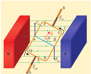
Consider a rectangular loop PQRS carrying current (I) is placed in a uniform magnetic field (\mathbf{B}). Let (a) and (b) be the length and breadth of the rectangular loop respectively. The unit vector (\hat{n}) normal to the plane of the loop makes an angle (\theta) with the magnetic field as shown in Figure 3.57.

The magnitude of the magnetic force acting on the current-carrying arm PQ is (F = IaB \sin(\theta/2)). The direction of the force is found using the right-hand cork screw rule and its direction is upwards.
The magnitude of the force on the arm QR is (F = I bB \cos(\pi\theta/2)) and its direction is as shown in Figure 3.57. The magnitude of the force on the arm RS is (F = IaB \sin(\pi/2)) and its direction is downwards. The magnitude of the force acting on the arm SP is (F = I bB \cos(\pi\theta/2)) and its direction is also as shown in Figure 3.57.
Since the forces (F_{QR}) and (F_{SP}) are equal, opposite, and collinear, they cancel each other. But the forces (F_{PQ}) and (F_{RS}), which are equal in magnitude and opposite in direction, do not act along the same straight line. Therefore, (F_{PQ}) and (F_{RS}) constitute a couple which exerts a torque on the loop.
\( \tau_{\text{PQ}} = bIaB \sin(\theta/2)\)and it points in the direction of AB. The magnitude of the torque acting on the arm RS about AB is
\( \tau_{\text{RS}} = bIaB \sin(\pi/2)\)and points also in the same direction AB as shown in Figure 3.58.
The total torque acting on the entire loop about an axis AB is given by
\( \tau = \frac{b}{2} F_{PQ} + \frac{b}{2} F_{RS} = \frac{b}{2} IaB \sin(\theta) + \frac{b}{2} IaB \sin(\theta) = IAB \sin(\theta)\)In vector form,
\( \boldsymbol{\tau} = (\mathbf{IA}) \times \mathbf{B}\)The above equation can also be written in terms of the magnetic dipole moment,
\( \boldsymbol{\tau} = \boldsymbol{\mu} \times \mathbf{B}\)where (\boldsymbol{\mu} = I\mathbf{A}).
The tendency of the torque is to rotate the loop so as to align its normal vector with the direction of the magnetic field.
If there are (N) turns in the rectangular loop, then the torque is given by
\( \tau = NIAB \sin(\theta)\)Special cases: (a) When (\theta = 90^\circ) or the plane of the loop is parallel to the magnetic field, the torque on the current loop is maximum.
\( \tau_{\text{max}} = IAB\)(b) When (\theta = 0^\circ/180^\circ) or the plane of the loop is perpendicular to the magnetic field, the torque on the current loop is zero.
Moving coil galvanometer
Moving coil galvanometer is a device which is used to detect the flow of current in an electrical circuit.
Principle: When a current carrying loop is placed in a uniform magnetic field, it experiences a torque.
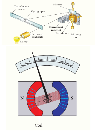
Construction: A moving coil galvanometer consists of a rectangular coil PQRS of insulated thin copper wire. The coil contains a large number of turns wound over a light metallic frame. A cylindrical soft-iron core is placed symmetrically inside the coil as shown in Figure 3.59. The rectangular coil is suspended freely between two pole pieces of a horse-shoe magnet.
The upper end of the rectangular coil is attached to one end of fine strip of phosphor bronze and the lower end of the coil is connected to a hair spring which is also made up of phosphor bronze. In a fine suspension strip, a small plane mirror is attached in order to measure the deflection of the coil with the help of lamp and scale arrangement. The other end of the mirror is connected to a torsion head. In order to pass electric current through the galvanometer, the suspension strip and the spring (S) are connected to terminals.
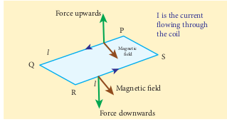
Working: Consider a single turn of the rectangular coil PQRS whose length is (l) and breadth (b). (PQ = RS = l) and (QR = SP = b). Let (I) be the electric current flowing through the rectangular coil PQRS as shown in Figure 3.60. The horse-shoe magnet has hemi - spherical magnetic poles which produces a radial magnetic field. Due to this radial field, the sides QR and SP are always parallel to the magnetic field (\mathbf{B}) and experience no force. The sides PQ and RS are always perpendicular to the magnetic field and experience equal forces in opposite directions. Due to this, torque is produced.
For single turn, the deflecting torque is
\( \tau = bF = bBIl = (lb) BI = ABI\)since the area of the coil, (A = lb). For a coil with (N) turns, we get

Due to this deflecting torque, the coil gets twisted and restoring torque (also known as restoring couple) is developed. Hence the moment of the restoring torque is proportional to the amount of twist (\theta). Thus
\( \tau = K\theta \, \text{(3.70)}\)where (K) is the restoring couple per unit twist.
At equilibrium, the deflecting couple must be equal to the restoring couple. Therefore we get,
\( NABI = K\theta\) \( \Rightarrow I = \frac{K}{NAB} \theta \, \text{(3.71)}\)(or) ( I = G\theta )
where ( G = \frac{K}{NAB} ) is called galvanometer constant or current reduction factor of the galvanometer.
Since the suspended moving coil galvanometer is very sensitive, we have to handle with high care while doing experiments. Most of the galvanometer we use are pointer type moving coil galvanometer.

[ \text{Force upwards} ]
[ \text{Force downwards} ]
[ \text{Magnetic field} ]
[ I \text{ is the current flowing through the coil} ]
[ \begin{array}{l} \ \text{Figure of merit of a galvanometer is defined as the current required to} \ \text{produce a deflection of one scale division in the galvanometer.} \end{array} ]
Sensitivity of a galvanometer: The galvanometer is said to be sensitive if it shows a large scale deflection even for a small current passed through it or a small voltage applied across it.
Current sensitivity: It is defined as the deflection produced per unit current flowing through the galvanometer.
\( I_s = \frac{NAB}{K}\) \( \Rightarrow I_s = \frac{(5)(2 \times 10^{-2})(4 \times 10^{-2})}{4 \times 10^{-9}} = 10^6 \, \text{divisions per ampere}\)Since (1 , \text{ampere} = 10^6) microamperes:
\( I_s = 1 \, \text{div/A} \, \mu\text{A}^{-1}\)Therefore,
\( I_s = (1 \, \text{div/A} \, \mu\text{A}^{-1})^{-1} = -10^{-6} \, \text{A}^{-1} \, \mu\text{A}\)Voltage sensitivity: It is defined as the deflection produced per unit voltage applied across the galvanometer.
\( V_s = \frac{I_s}{\theta} = \frac{1 \, \text{div/A} \, \mu\text{A}^{-1}}{50} = 2 \times 10^{-3} \, \text{div/(V)}\)Resistance of the galvanometer:
\( R = \frac{V}{I_g} = \frac{50 \times 10^{-3}}{10^{-6}} = 5 \times 10^4 \, \Omega\)Note: In part (b), the voltage sensitivity is calculated by dividing the current sensitivity by the number of divisions ((\theta)) for full-scale deflection.
Feel free to ask if you have any further questions or if there’s anything else I can assist you with!
EXAMPLE 3.26
The resistance of a moving coil galvanometer is made twice its original value in order to increase current sensitivity by 50%. Find the percentage change in voltage sensitivity.
Solution:
Voltage sensitivity is given by ( V = I \cdot R_g ).
When the resistance is doubled, then the new resistance is ( R’_g = 2R_g ).
Increase in current sensitivity is given by:
\( \frac{\Delta I}{I} = \frac{R'_g - R_g}{R_g} \times 100\)Substitute ( R’_g = 2R_g ) into the formula:
\( \frac{\Delta I}{I} = \frac{2R_g - R_g}{R_g} \times 100 = 50\%\)The new voltage sensitivity is:
\( V' = I \cdot R'_g = I \cdot 2R_g\)Hence, the percentage change in voltage sensitivity is:
\( \frac{\Delta V}{V} = \frac{V' - V}{V} \times 100 = \frac{I \cdot 2R_g - I \cdot R_g}{I \cdot R_g} \times 100 = 100\%\)Conclusion:
The voltage sensitivity increases by 100% when the resistance of the galvanometer is made twice its original value.
Feel free to ask if you have any further questions or if there’s anything else I can assist you with!